
Orbi R1 Smart Ring.
A production-intent wearable platform engineered around optical sensing, bioelectrodes, flexible electronics, low-power firmware and a precision charging case.

At a glance
- The brief
- Smart rings fail when the product is treated as a small electronics enclosure rather than a body-worn measurement system.
- What we delivered
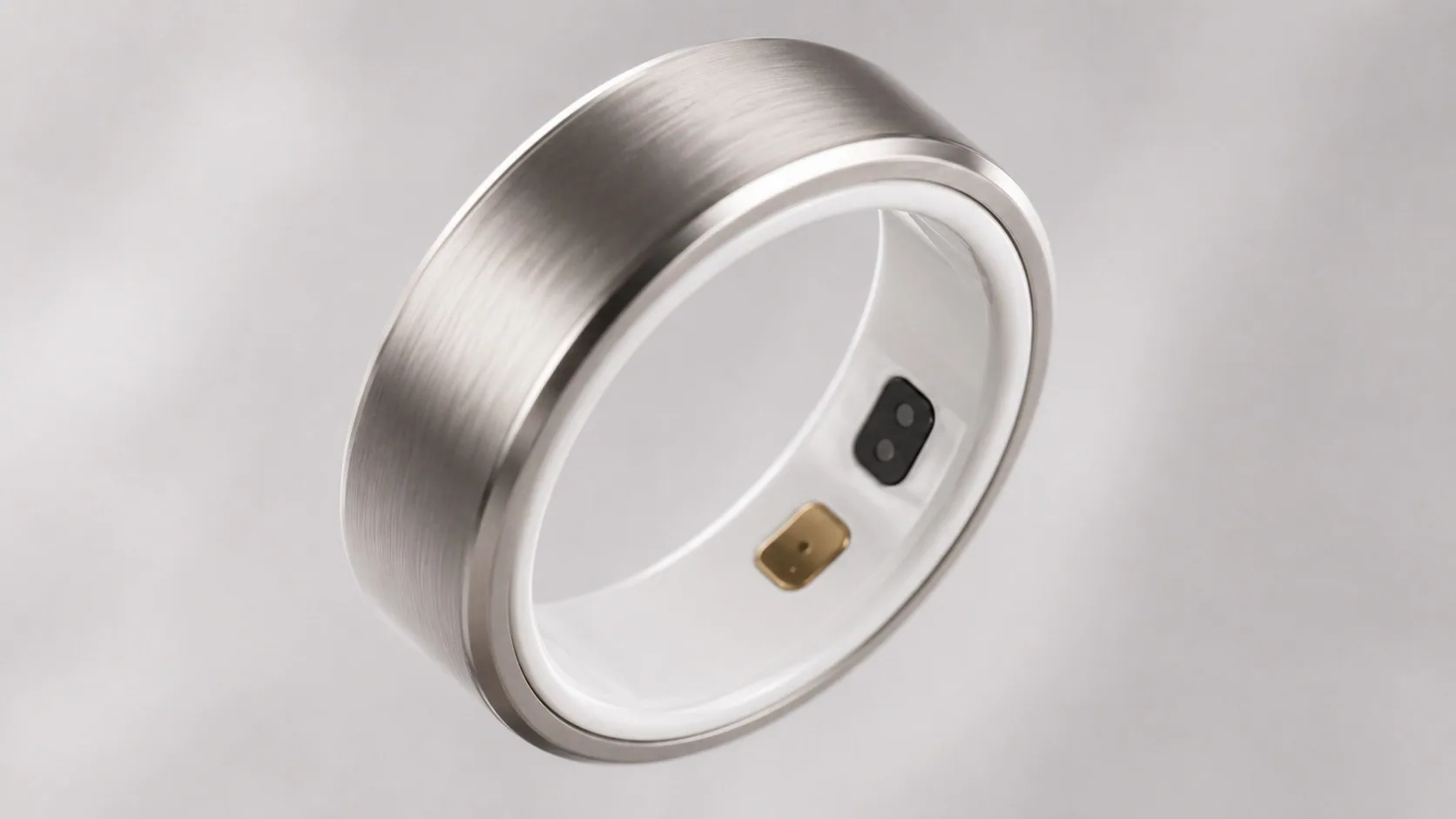
- Orbi R1 was developed as a compact smart ring that combines physiological sensing with the proportions, materials and comfort expectations of everyday jewellery.
Key figures
Turning continuous sensing into an object people will actually wear.
Orbi R1 was developed as a compact smart ring that combines physiological sensing with the proportions, materials and comfort expectations of everyday jewellery.
The engineering challenge was not simply placing sensors inside a ring. It was creating stable skin contact, maintaining optical signal quality, managing RF performance around a metal shell, fitting power and electronics into a curved envelope, and protecting the assembly against sweat and daily wear.
Engineering detail Show
Surge Robotics' role
Surge Robotics carried the product through system definition, industrial design, mechanical architecture, sensor integration, flexible PCB packaging, embedded firmware planning, charging-case development, verification planning and production handoff.
Product positioning
BLE
Low-energy wireless architecture
Miniaturisation was only one part of the problem.
Smart rings fail when the product is treated as a small electronics enclosure rather than a body-worn measurement system.
Engineering detail Show
Optical readings are affected by movement, skin contact, ambient light, skin tone, perfusion and sensor pressure.
A device worn day and night must avoid pressure points, sharp transitions, excess width and local heat.
Battery capacity is constrained by ring size while sensing, processing and BLE remain energy intensive.
The user's body and titanium shell can detune or shield the antenna.
Sweat, water, cosmetics, impact and repeated charging must not degrade the product.
The curved stack must be assembled, calibrated, sealed and inspected repeatably.
Premium product language without turning the ring into a fragile or costly prototype-only assembly.
Stable sensor contact across finger sizes and natural daily movement without excessive tightness.
Mechanical, optical, electrical and RF requirements compete for the same millimetres of internal volume.
Health-related insights require transparent quality controls and careful separation of wellness claims from medical claims.
A layered wearable architecture with jewellery-grade external surfaces.
Engineering detail Show
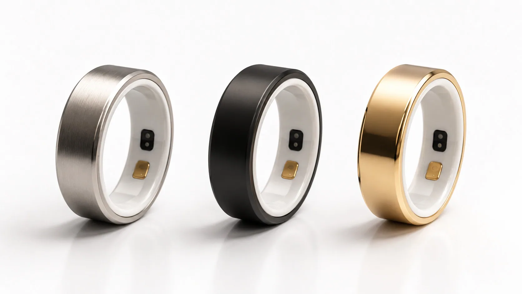
Grade 5 titanium provides a premium surface, high strength-to-weight ratio and a durable cosmetic finish.
A smooth zirconia inner band supports comfort, electrical isolation and repeatable sensor windows.
A flexible PCB, micro-battery, optical channels, electrode interfaces and BLE antenna follow the ring geometry.
One integrated system across sensing, power, mechanics, firmware and charging.
Engineering detail Show
Optical windows, electrode zones, ceramic geometry and fit pressure create the measurement interface.
Dual PPG channels and bioelectrode inputs capture optical pulse-wave and bio-potential / conductance signals.
Low-power MCU schedules sampling, manages sensors, filters events, stores data and controls operating states.
Curved micro-battery, power-management ICs, charge protection and aggressive duty-cycling support multi-day targets.
BLE transfers processed metrics, device status, configuration and firmware updates to a companion application.
A guided upright dock creates repeatable contact, protects the ring and extends usable time between USB-C charging sessions.
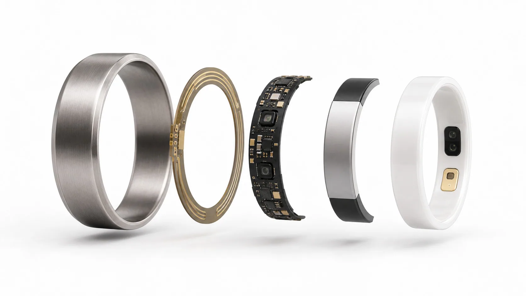
The product was engineered as a curved, service-controlled stack.
Engineering detail Show
Titanium shell and cosmetic edge control
Flex PCB, optical sensors, power management and antenna
Curved micro-battery and charging contacts
Zirconia band, optical windows and PVD electrode surfaces
Optical performance depended on geometry, not only sensor selection.
The inner-band optical module was designed to control emitter-detector spacing, skin pressure, ambient-light rejection and internal optical crosstalk.
Engineering detail Show
- Flush-mounted optical windows reduce snagging and uncontrolled air gaps.
- Red and infrared channels support pulse-wave and oxygenation-related measurement development.
- Mechanical ribs and opaque barriers isolate emitters from detectors inside the curved cavity.
- Sampling profiles adapt to motion state, required metric and available power budget.
- Signal-quality scoring prevents weak or corrupted data from being presented as confident insight.
Critical validation variables
Electrical contact was designed as a controlled interface, not a decorative insert.
The gold-PVD electrode architecture supports low-noise skin contact for bio-potential and conductance measurement development. Reliable performance requires electrode geometry, surface finish, contact pressure and analogue front-end design to be treated together.
Engineering detail Show
Define how electrode pairs complete the measurement path during normal wear or an intentional touch action.
High input impedance, input protection, common-mode control and low-noise amplification preserve microvolt-level signals.
Motion, dry skin, sweat and intermittent contact are identified through impedance and quality checks.
PVD thickness, adhesion, corrosion resistance and cleaning compatibility are verified over repeated wear cycles.
Designed to support short-duration single-channel bio-potential capture with deliberate user contact and quality gating.
Skin-conductance sensing can support stress and arousal research when interpreted within a broader physiological model.
Input protection, leakage-current control and material biocompatibility are built into the electrical and mechanical design.
Physiological signals do not automatically create clinically valid measurements; algorithm and study evidence govern claims.
Every fraction of a millimetre affected comfort, sealing and signal quality.
Engineering detail Show
The internal cavity was divided into optical, battery, electronics, antenna and charging zones. Component height and bend radius were controlled against the ceramic inner diameter and titanium shell.
The outer titanium ring carries daily contact loads while the ceramic interface protects sensors and electronics from direct abrasion and edge impact.
Parting lines, adhesive lands, optical windows and charging contacts were arranged to minimise leak paths and support controlled dispensing and inspection.
Ring size, ceramic shrinkage, PCB placement and shell machining tolerances were combined into a closed stack-up rather than assessed independently.
Size governance
Premium materials were selected for functional reasons, not only appearance.
Engineering detail Show
| Element | Engineering role |
|---|---|
| Grade 5 titanium shell | High stiffness, low mass, corrosion resistance and durable premium finish. |
| Zirconia ceramic inner band | Biocompatible skin surface, electrical isolation, optical-window stability and scratch resistance. |
| Gold-PVD electrode | Low-resistance skin interface with controlled corrosion and wear performance. |
| Polyimide flexible PCB | Curved routing, compact assembly and controlled antenna/sensor placement. |
| Engineering adhesive / sealant | Structural retention, environmental sealing and strain distribution. |
Finish variants
The flexible PCB became the mechanical backbone of the electronic system.
Engineering detail Show
Optical drivers, photodiode receivers and bio-potential analogue circuitry are partitioned to reduce digital and power noise.
Coordinates sensor timing, local processing, storage, BLE events, fault monitoring and power states.
Battery protection, regulation, fuel estimation, charging control and brownout behaviour are designed as a single subsystem.
Rigid component islands, bend zones, copper balancing and strain relief protect solder joints during forming and assembly.
Ground strategy, return paths, switching-edge control and shielding boundaries reduce interference with sensitive analogue channels.
Programming, current measurement, optical response, electrode impedance, BLE and charge tests are accessible before final closure.
"In a wearable this small, PCB layout, antenna behaviour and mechanical packaging cannot be developed as separate tasks."
Battery life was created by system behaviour, not only cell capacity.
The reference architecture uses an approximately 17 mAh, 3.8 V curved micro-battery. The final chemistry and supplier specification remain controlled BOM items.
Engineering detail Show
High-energy optical modes run only when required by the measurement plan.
Raw data is reduced locally so BLE transfers are short and scheduled.
Sampling intensity changes with motion, contact quality and battery state.
Unused peripherals, clocks and rails are shut down between measurement events.
Overcharge, over-discharge, short-circuit, thermal and brownout conditions are defined with safe recovery behaviour.
State-of-charge is modelled against load profile, temperature, ageing and charge history rather than voltage alone.
Charge rate and high-current sensing modes are constrained to prevent perceptible skin-side heating.
Capacity retention, swelling, charge-cycle life and storage behaviour are included in supplier qualification.
Wireless performance was engineered around a metal ring and the human body.
Engineering detail Show
Timed optical and electrode sampling
Filtering, quality scoring and feature extraction
Short encrypted data transfers and configuration
Trend visualisation, settings and updates
The polyimide antenna trace is positioned away from the highest-loss metal and tissue zones. Matching is tuned on the assembled product and on-body, not only on a bench fixture.
Advertising intervals, connection windows, packet size and retry logic are balanced against user experience and energy budget.
Authenticated pairing, encrypted transport, controlled device identifiers and secure firmware-update logic protect user data and product integrity.
The ring buffers essential data and synchronises later, preventing short phone disconnections from creating gaps in the user record.
Privacy-by-design
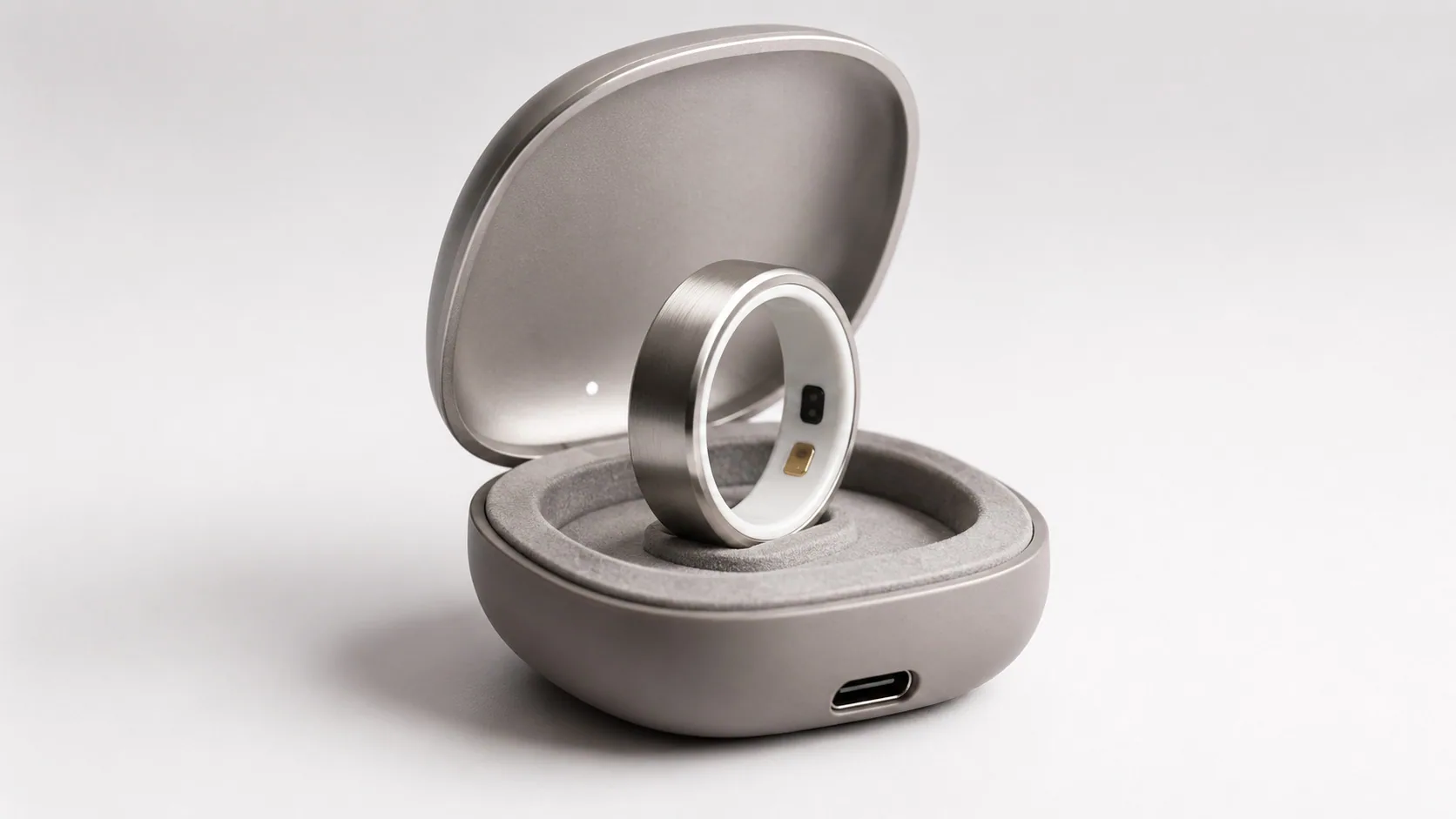
The case is part of the product system, not packaging.
The charging case protects the ring, creates a repeatable charging interface and improves the everyday ownership experience.
Engineering detail Show
- Guided upright post aligns the ring and prevents unstable contact.
- Felt-lined cavity controls cosmetic damage and movement during transport.
- Spring or compliant contacts accommodate ring and assembly tolerances.
- Magnetic lid closure provides tactile confirmation without stressing the ring.
- USB-C input, charge management and status LED provide a familiar charging model.
- Case electronics support contact detection, current control and fault indication.
Wearability was treated as an engineering requirement.
Engineering detail Show
Rounded edges, polished ceramic and controlled sensor projection reduce local pressure during sleep and daily tasks.
Ring sizing and internal geometry minimise rotation while avoiding excessive compression that can affect circulation and signal quality.
Heat-generating components are distributed and firmware limits sustained high-power operation near the skin.
Sensor zones and case docking provide natural cues for correct wearing and charging orientation.
Continuous surfaces and protected interfaces reduce residue traps and support routine cleaning.
Fit and sensing performance are evaluated across finger sizes, skin tones, activity levels and environmental conditions.
A deterministic state machine controls sensing, energy and data quality.
Engineering detail Show
| 01 Boot + self-test | Memory, sensors, battery, charge state and calibration records are checked. |
|---|---|
| 02 Wear detection | Optical/contact cues determine whether the ring is worn and signal capture is meaningful. |
| 03 Scheduled sensing | Low-power and high-resolution profiles are triggered by time, motion and metric requirements. |
| 04 Quality gating | Artifacts, saturation, weak contact and inconsistent channels are flagged before metrics are accepted. |
| 05 Sync + update | Processed records, diagnostics and configuration are exchanged through controlled BLE sessions. |
| 06 Sleep / fault | Deep sleep minimises energy; fault states protect the battery and preserve diagnostic evidence. |
Algorithm boundary
Measurement confidence was designed into the data pipeline.
Engineering detail Show
Ambient subtraction, dark-current compensation, baseline correction and digital filtering prepare optical and electrode channels.
Movement classification and signal morphology identify periods where physiological inference is unreliable.
Channel saturation, pulse consistency, contact stability, noise floor and inter-channel agreement produce a confidence score.
Factory optical/electrode calibration is combined with device-level offsets and controlled firmware coefficients.
Bench and human-subject studies compare ring outputs against controlled reference instruments under defined protocols.
Sensor configuration, algorithm version and calibration data are traceable so results can be reproduced and audited.
Core principle
Engineering detail Show
Ring
| Product | Orbi R1 smart ring |
|---|---|
| Outer material | Grade 5 titanium, brushed matte reference finish |
| Inner material | Zirconia ceramic (ZrO₂), smooth polished finish |
| Reference size | Size 10, approx. Ø22.2 mm outer reference |
| Band width | 8.0 mm reference |
| Wall thickness | 2.6 mm reference |
| Weight | Approx. 4.0 g at reference size |
| Wireless | Bluetooth Low Energy |
Sensors, power and case
| Optical sensing | Dual PPG sensor architecture with red / IR channels |
|---|---|
| Bioelectrode | Gold-PVD coated electrode interface for ECG / conductance development |
| Battery | Approx. 17 mAh, 3.8 V curved micro-battery reference |
| PCB | Curved flexible polyimide circuit assembly |
| Antenna | Integrated polyimide BLE trace |
| Case | 55 × 45 × 28 mm reference; PC/ABS base and aluminium lid |
| Case charging | USB-C input with status indicator |
| Environmental | Final rating governed by sealed-production validation |
SPECIFICATION GOVERNANCE: DIMENSIONS, MASS, BATTERY, OPERATING TIME AND ENVIRONMENTAL RATING MUST BE RELEASED BY PRODUCT SIZE AND PRODUCTION REVISION. RENDERED IMAGES ARE NOT A SUBSTITUTE FOR CONTROLLED DRAWINGS, BOMS AND TEST REPORTS.
One integrated team across the complete wearable product stack.
Engineering detail Show
User needs, product claims, success metrics, size strategy and commercial constraints.
Form language, finish variants, comfort surfaces, charging experience and visual integration.
Curved packaging, material stack, tolerance analysis, sealing, assembly and size variants.
Sensor architecture, analogue front ends, flexible PCB, power management, antenna and charging interfaces.
State machine, sensor drivers, power modes, BLE, diagnostics and secure update framework.
Signal-quality pipeline, calibration architecture, reference testing and algorithm version control.
Mechanical samples, electronics builds, calibration fixtures, charging prototypes and integration support.
Test plans, risk controls, battery/RF pathways, skin-contact materials and claims discipline.
A stage-gated programme connected each design decision to evidence.
Engineering detail Show
01 / w1-3
Claims, use cases, size strategy, sensing feasibility, power budget and risk register.
02 / w3-6
Product form, material stack, sensor geometry, electronics partitioning and case concept.
03 / w6-11
Flex PCB, mechanical samples, optical/electrode test fixtures and firmware bring-up.
04 / w11-15
Ring and case integration, calibration, power profiling, BLE and early wear testing.
05 / w15-21
Environmental, mechanical, battery, RF, signal-quality and usability verification.
06 / w21-24
Production files, fixtures, inspection plans, supplier qualification and pilot-build gate.
Feasibility evidence
Architecture frozen
Integrated EVT functional
DVT requirements passed
Pilot package released
The test plan covers the product, the data and the user interface to the body.
Engineering detail Show
| Area | Representative verification | Release evidence |
|---|---|---|
| Mechanical | Compression, impact, torsion, drop, surface wear, ring-size gauges and case hinge/dock cycling | Test report, dimensional inspection, failure analysis |
| Environmental | Sweat, splash, cleaning chemicals, humidity, thermal cycling and condensation exposure | Ingress evidence, post-test functional and cosmetic inspection |
| Optical sensing | Signal-to-noise, ambient rejection, motion artifact, skin-tone range, fit and perfusion conditions | Dataset, quality thresholds, reference comparison |
| Bioelectrodes | Contact impedance, noise floor, dry/wet skin, coating wear and intentional-touch usability | Electrical report, coating durability and human-factors record |
| Power | Runtime profiles, charge time, thermal rise, cycle ageing, protection faults and storage | Power budget, battery qualification and safety record |
| RF + firmware | On-body range, reconnection, coexistence, update recovery, data integrity and secure pairing | RF report, firmware test log and traceability matrix |
| Production | Programming, calibration, optical test, electrode test, current test and final functional inspection | Fixture GR&R, station limits and yield dashboard |
Key risks were converted into design controls and measurable tests.
Engineering detail Show
| Risk | Engineering control | Validation |
|---|---|---|
| Motion-corrupted PPG | Mechanical contact control, adaptive sampling, motion context and signal-quality gating | Controlled motion protocols and reference-device comparison |
| RF loss from titanium / body | Antenna keep-out, matching network, shell segmentation strategy and on-body tuning | Radiated and on-body connection testing across sizes |
| Battery swelling or heat | Qualified cell, charge limits, thermal monitoring, cavity allowance and protective shutdown | Cycle ageing, abuse tests and skin-side thermal measurement |
| Water / sweat ingress | Controlled bond line, reduced penetrations, sealed windows and post-assembly inspection | Pressure/splash/sweat tests and teardown analysis |
| Electrode degradation | Coating specification, rounded geometry and cleaning compatibility | Abrasion, corrosion and impedance tests |
| Size-related assembly variation | Size-specific CAD/BOM, tolerance analysis and dedicated gauges | First-article inspection and capability studies by size |
| Unsubstantiated health claims | Claims matrix, dataset governance, quality thresholds and regulatory review | Traceable evidence package and approved product language |
The final design was structured around repeatable assembly and calibration.
Engineering detail Show
CNC machining supports early volume and finish control; higher-volume processes require a separate tooling and economics review.
Zirconia forming, sintering shrinkage, grinding and polishing are controlled through size-specific process capability.
Panelisation, stiffeners, controlled bend forming and optical alignment fixtures protect yield.
Automated adhesive dispensing, bond-line inspection, cure control and leak screening create traceable closure.
Optical response, electrode impedance, power current and BLE identity are recorded against each serial number.
Charge, sensor, wireless, current, cosmetic and dimensional checks are combined into a controlled end-of-line sequence.
Production package
Controlled CAD and drawings
Released BOM / AVL
Flex PCB fabrication and assembly data
Firmware release package
Calibration and test fixtures
Inspection plans
Assembly work instructions
Risk and verification records
A wearable product engineered as one coherent system.
Orbi R1 demonstrates Surge Robotics' approach to developing compact products where industrial design, sensing physics, flexible electronics, power, firmware and manufacturing must be resolved together.
Developing a wearable or connected health product?

Have a product you’d like us to engineer?
Share the product, challenge or technical risk you are facing. We’ll come back with a clear technical next step — no sales pitch disguised as discovery.