
Modular E-Bike Conversion Kit.
A removable friction-drive electrification system engineered as a complete product: motor drive, battery, quick-lock mounting, rider controller, sensing, safety logic and production documentation.
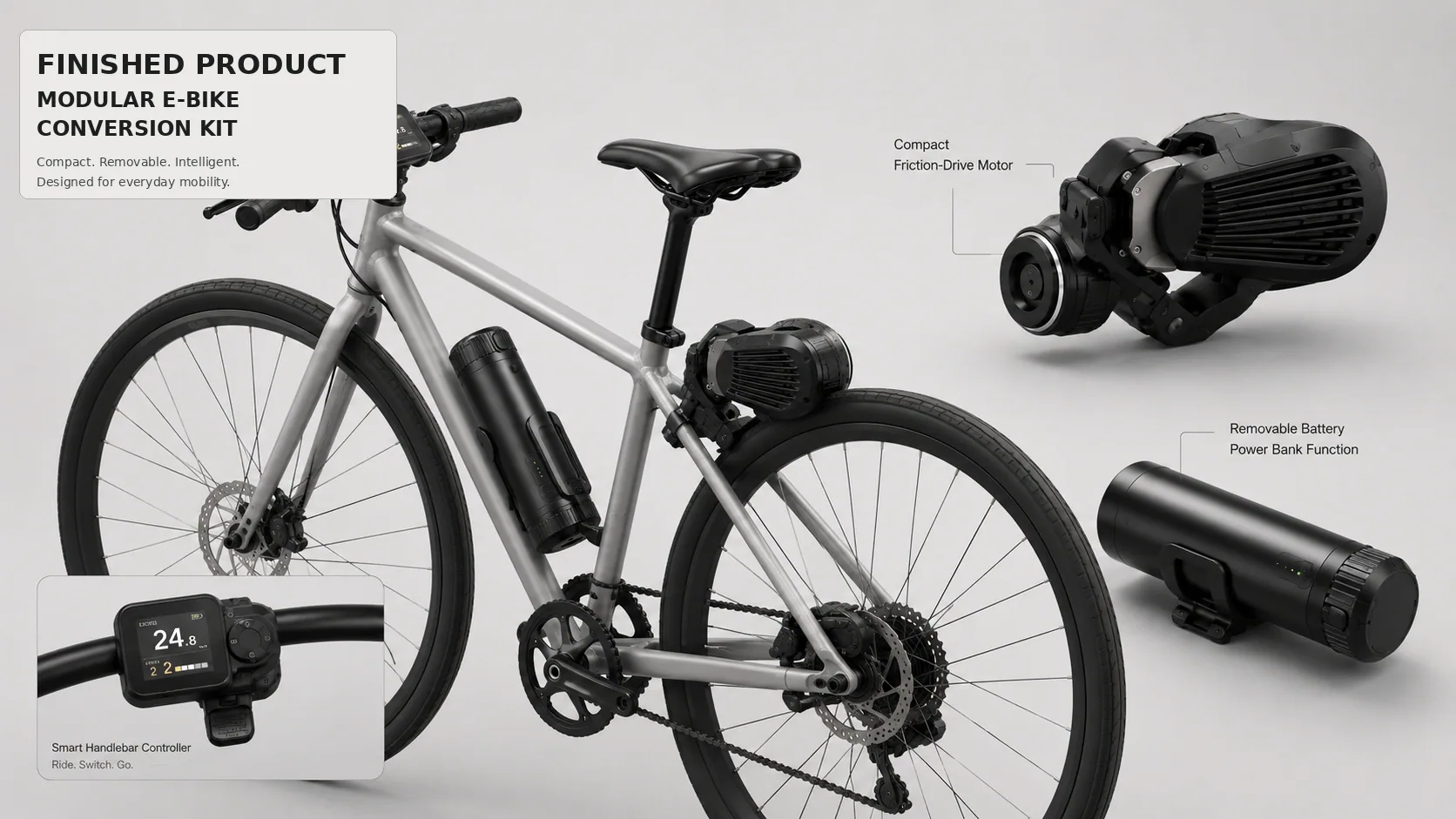
At a glance
- The brief
- Conventional e-bike conversion solutions typically require wheel replacement, permanent drivetrain changes or complex installation. The product needed to preserve the existing bicycle, remain removable and create a credible consumer product rather than an exposed engineering add-on.
- What we delivered
- The project required more than mounting a motor onto a bicycle. The finished product had to deliver controlled tire traction, safe power delivery, rapid installation, removable energy storage, intuitive rider control and compatibility with conventional bicycle geometries.
Key figures
From retrofit idea to a finished, integrated mobility product.
The project required more than mounting a motor onto a bicycle. The finished product had to deliver controlled tire traction, safe power delivery, rapid installation, removable energy storage, intuitive rider control and compatibility with conventional bicycle geometries.
Surge Robotics developed the complete system architecture and converted it into an integrated product platform with defined mechanical interfaces, electrical architecture, embedded control, user interaction, installation requirements and production-ready engineering documentation.
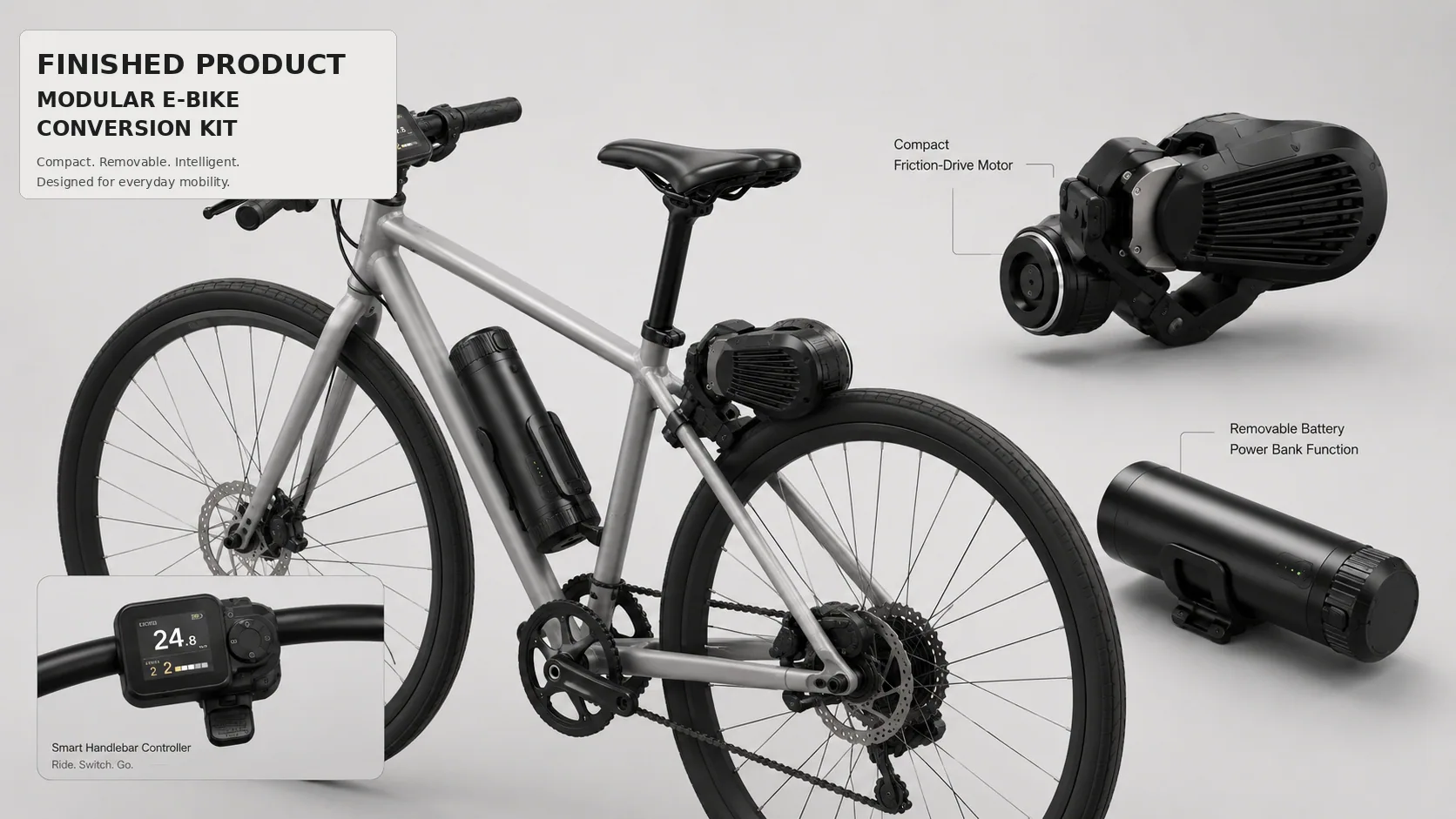
Engineering detail Show
Target wheel compatibility
250–750 w
Configurable power platform
- No wheel replacement or permanent frame modification
- Pressure-controlled tire contact for predictable traction
- Quick-lock mounting and removable battery architecture
- Integrated rider display, assist control and safety interlocks
- Designed for service access, repeatable assembly and product variants
Engineering detail Show
Problem definition
Conventional e-bike conversion solutions typically require wheel replacement, permanent drivetrain changes or complex installation. The product needed to preserve the existing bicycle, remain removable and create a credible consumer product rather than an exposed engineering add-on.
Critical constraints
- Variable frame tube diameters and rear-triangle geometry
- Changing tire radius, deflection and road vibration
- Limited packaging volume near the rear wheel
- Heat, water, dust and continuous vibration exposure
- Safe torque control during installation, tilt and fall events
- Market-specific power and assisted-speed requirements
Engineering success criteria
Install on representative 650C-700C bicycles with tire widths up to 50 mm and defined frame clearances.
Maintain controlled roller pressure without excessive tire wear, slip, heating or noise.
Prevent torque output until mechanical engagement, system state and rider conditions are confirmed.
Resolve enclosure design, serviceability, cable routing, assembly sequence, manufacturing methods and documentation.
A distributed product architecture designed for installation, service and upgradeability.
The finished system separates rider input, power and sensing, energy storage and mechanical torque transfer into replaceable modules connected through a protected harness.
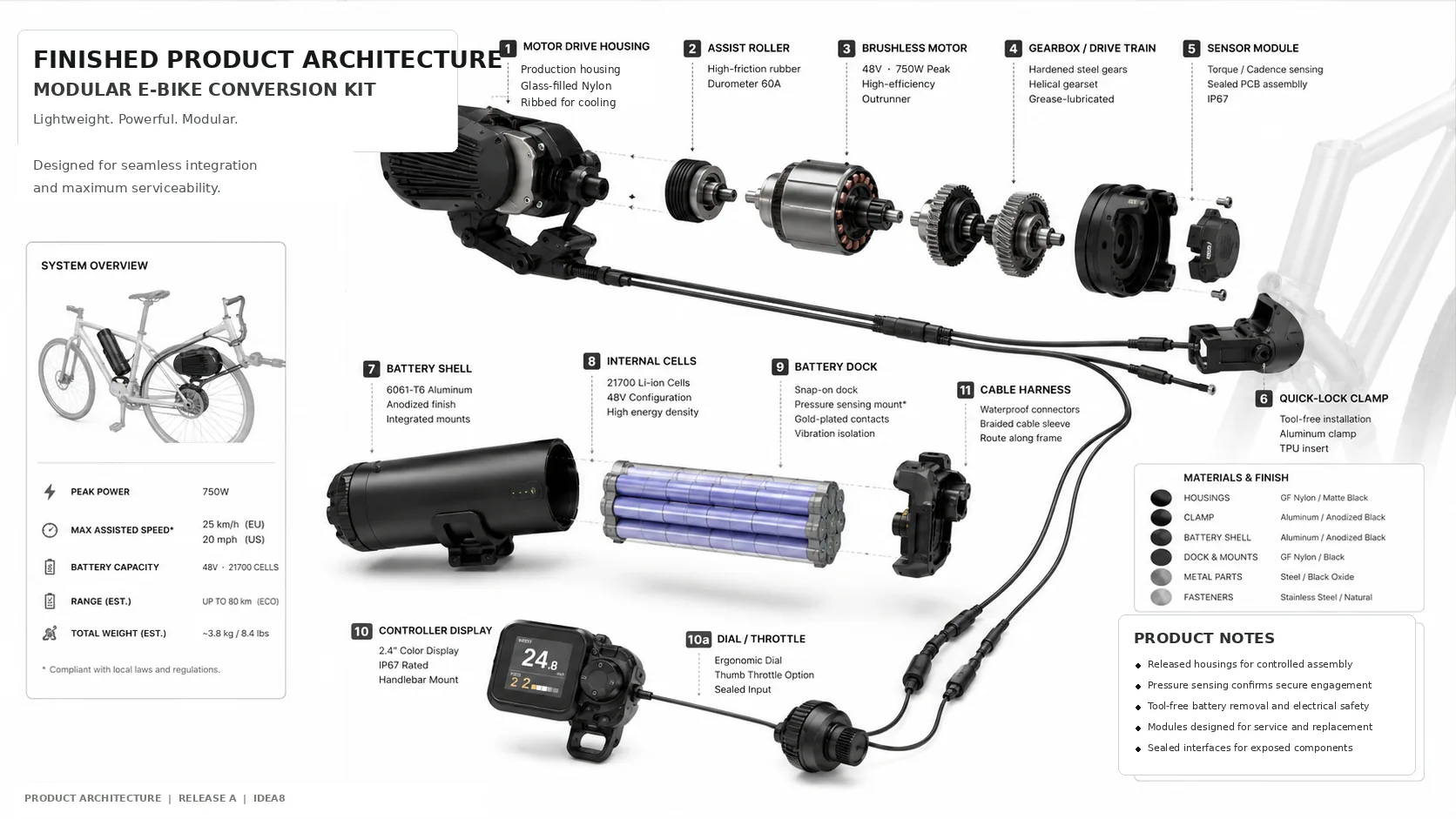
Engineering detail Show
Speed display, assist selection, mode control and rider input at the handlebar.
Battery management, motor control, pressure confirmation, speed sensing and IMU-based logic.
Motor, gearbox, compliant pressure arm and high-friction roller transferring torque to the tire.
Cylindrical pack with integrated BMS, protected contacts and a positive-lock dock.
Separates the bicycle interface from the drive module for rapid installation and service.
Water-resistant connectors, strain relief and routing designed around moving bicycle components.
Pressure-controlled friction drive was the defining engineering problem.
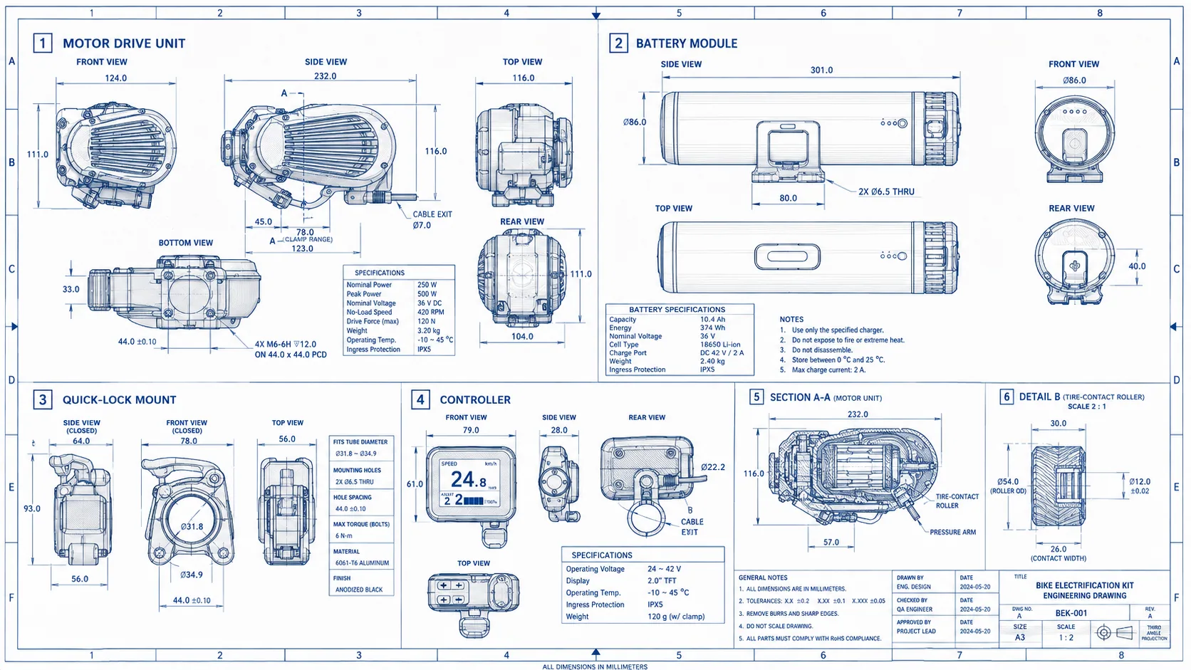
The motor unit combines a brushless motor, reduction stage, tire-contact roller, pressure arm and sealed housing. The architecture converts motor speed into usable wheel torque while continuously managing contact with a deformable rotating tire.
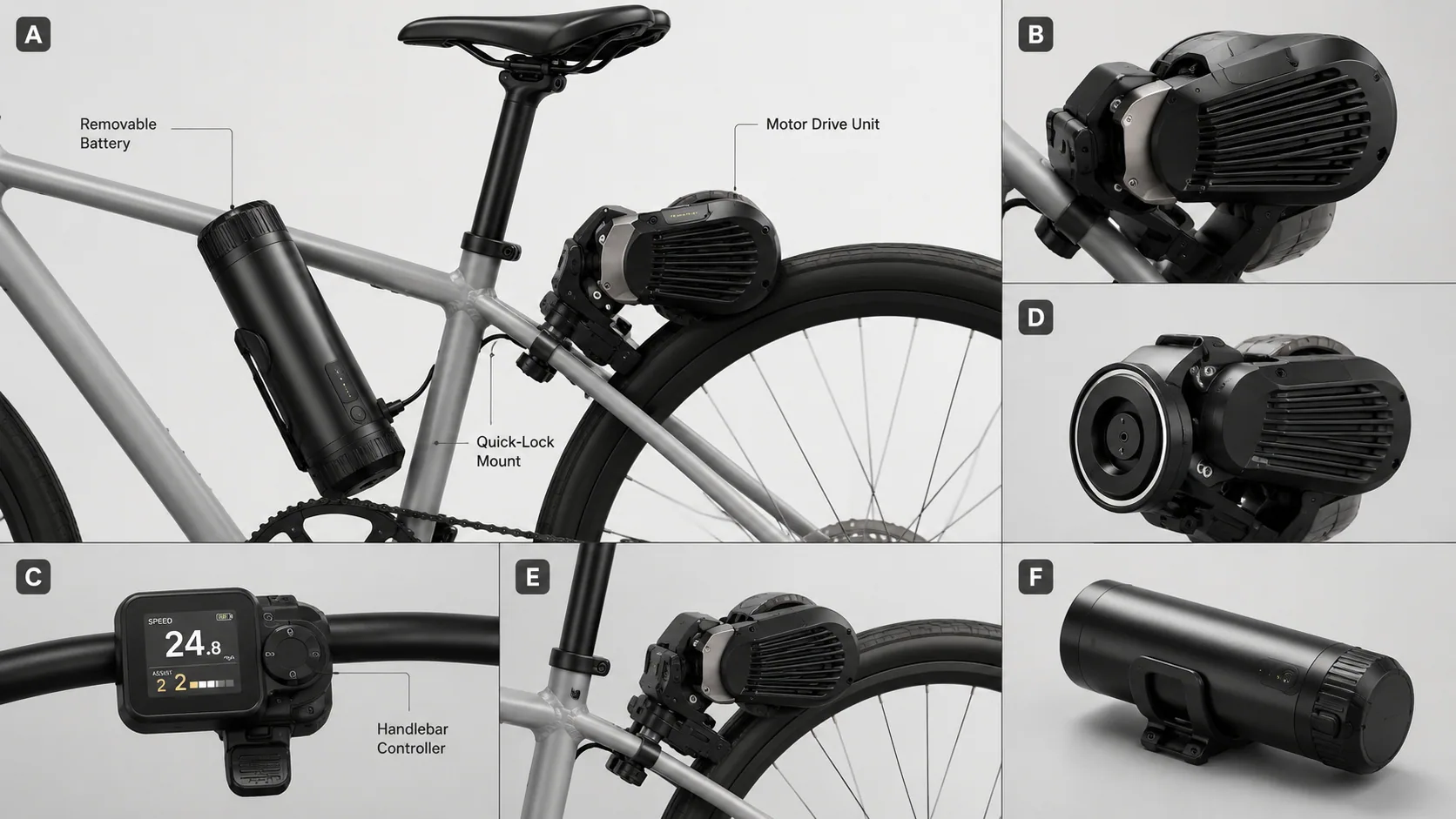
Engineering detail Show
Drive engineering decisions
- High-friction replaceable roller surface
- Spring-loaded pressure arm to maintain contact over tire runout
- Reduction gearbox sized around assist torque and roller speed
- Ribbed enclosure and internal thermal path for motor/controller heat
- Serviceable transmission and roller components
Designed around sustained assist without uncontrolled slip or excessive contact pressure.
The pressure mechanism follows tire deflection, frame motion and surface variation.
Drive torque is disabled when engagement, tilt, fall or control-state requirements are not satisfied.
The product is managed as an electrical system, not a motor with a switch.
Engineering detail Show
Li-ion pack architecture, cell protection, current limits, charging interface, pack state and protected output contacts.
Power-stage selection, speed and torque command, current limiting, thermal protection and fault-state handling.
Pressure/engagement input, wheel speed, IMU-based tilt/fall detection and controlled start-up sequencing.
2-inch-class display, assist level selection, status indication, fault communication and ergonomic control placement.
Control-state logic
| State | System behaviour |
|---|---|
| Power-on self-check | Validate battery, controller, sensors, communication and throttle/assist neutral state. |
| Mount confirmation | Confirm mechanical engagement and required pressure before torque is enabled. |
| Assist active | Apply controlled output based on rider command, speed and configured market limits. |
| Fault / fall event | Remove drive torque, communicate the fault and require a safe reset condition. |
| Low battery / thermal limit | Derate output before shutdown to protect cells, controller and motor. |
Regional configuration
Installation was engineered as part of the product.
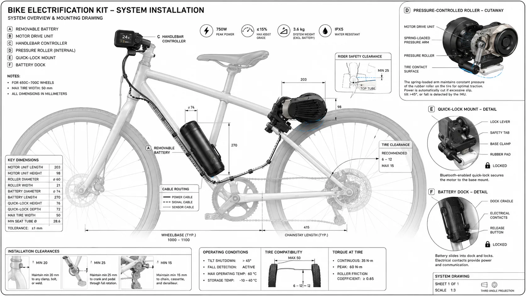
The quick-lock mount creates a controlled interface between the bicycle frame and the drive unit. A clamp, lock lever, safety tab and rubber isolation pad enable rapid attachment while controlling rotation, vibration and accidental release.
Engineering detail Show
- Tool-minimized installation sequence
- Defined tube-diameter and clearance envelope
- Repeatable motor-to-tire alignment
- Positive mechanical lock plus secondary safety feature
- Protected cable path away from chain, wheel and rider contact zones
- Battery dock with guided insertion, latch and protected electrical contacts
Engineering detail Show
Drive system
| Architecture | External pressure-controlled friction drive |
|---|---|
| Motor | Brushless motor with reduction gearbox |
| Power platform | 250 W nominal; 500–750 W peak depending on market |
| Electrical platform | 36–48 V architecture depending on variant |
| Motor module envelope | Approx. 232 × 124 × 116 mm |
| Roller | Approx. 54 mm OD × 26 mm contact width, replaceable |
| Ingress design | IPX5-class system target |
| Operating range | -10 to 45 °C reference |
Battery, control & compatibility
| Battery | Removable Li-ion module with BMS and positive-lock dock |
|---|---|
| Reference battery | 36 V, 10.4 Ah, 374 Wh engineering configuration |
| Battery envelope | Approx. Ø86 × 301 mm |
| Controller | 2.0-inch-class TFT with assist selection |
| Controller envelope | Approx. 79 × 61 × 28 mm |
| Wheel compatibility | 650C–700C target range |
| Maximum tire width | 50 mm |
| Assisted speed | Configured for regional requirements |
One integrated team across the complete product stack.
Engineering detail Show
Use case, target rider, installation model, product variants, success criteria and commercial constraints.
Subsystem boundaries, interfaces, power path, safety logic and service strategy.
Product language, user touchpoints, packaging, enclosure construction and visual integration.
Drive packaging, gearbox, roller, pressure arm, mount, battery dock, tolerances and service access.
Battery and power architecture, control electronics, sensing, protection, HMI and embedded logic.
Prototype builds, assembly, bench testing, bicycle integration, fault testing and iteration.
Material/process selection, fastener strategy, molded-part logic, machining requirements and assembly planning.
Drawings, BOM structure, cable definition, assembly intent, installation information and revision control.
Supplier package, inspection points, test fixtures, acceptance criteria and pilot-build support.
A stage-gated plan connecting engineering work to measurable release decisions.
Engineering detail Show
01 / w1-2
Requirements & compliance basis
02 / w2-4
Architecture & feasibility
03 / w4-8
Industrial & mechanical design
04 / w5-10
Prototype build & subsystem tests
06 / w13-17
Integration & design validation
07 / w17-21
DFM & pilot preparation
08 / w21-24
Release & production handoff
Have a similar product to build?
Engineering detail Show
| Gate | Phase | Primary activities | Release evidence |
|---|---|---|---|
| G0 | Requirements freeze | Use cases, bicycle envelope, performance targets, safety and regional constraints. | Approved PRD, system requirements, compliance matrix and risk baseline. |
| G1 | Architecture approval | Powertrain selection, module boundaries, battery platform, control concept and interface definition. | Architecture diagram, ICD, initial calculations and feasibility rigs. |
| G2 | Detailed design review | CAD, gearbox/roller, enclosure, PCB/electrical, firmware state machine and thermal strategy. | Design review record, released prototype drawings, BOM and procurement package. |
| G3 | EVT build acceptance | Subsystem prototypes, bench fixtures, firmware bring-up, mechanical fit and basic tests. | Working integrated prototypes, issue log and updated risk register. |
| G4 | DVT validation | Compatibility matrix, endurance, vibration, thermal, ingress, braking/coast, fault handling. | Verification report with pass/fail evidence and approved corrective actions. |
| G5 | Pilot / production release | DFM, assembly sequence, test fixtures, supplier feedback and process capability. | Production BOM, drawings, work instructions, inspection plan and release configuration. |

Have a product you’d like us to engineer?
Share the product, challenge or technical risk you are facing. We’ll come back with a clear technical next step — no sales pitch disguised as discovery.