
EVT Smart Helmet.
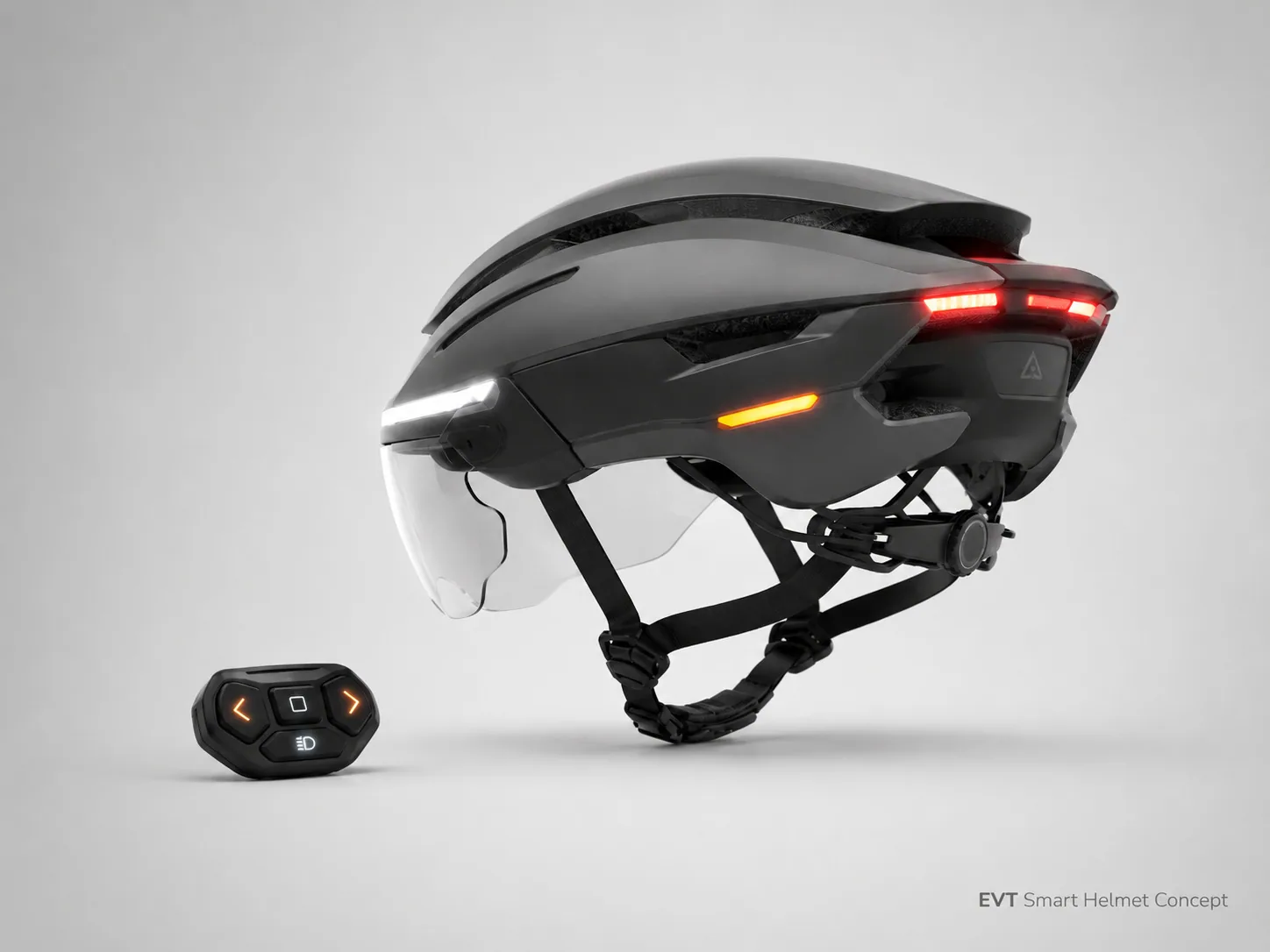
An integrated cycling safety platform combining impact protection, rider-visible lighting, IMU-based brake detection, a removable visor and a wireless handlebar controller.
At a glance
- The brief
- A helmet is an energy-management structure. Batteries, PCBs, fasteners and light modules cannot be placed wherever packaging is convenient; hard points, mass concentrations and voids can affect impact behaviour and comfort. Meanwhile, automatic brake lighting is harder than thresholding acceleration — head movement, road shock and climbing posture create signals that can look like braking.
- What we delivered
- The engineering challenge was not simply to add lights and electronics to a bicycle helmet. Every added component had to coexist with the impact liner, retention system, airflow paths, field of view, weight distribution and certification envelope of a safety-critical product.
Key figures
Safety equipment first. Connected product second.
The engineering challenge was not simply to add lights and electronics to a bicycle helmet. Every added component had to coexist with the impact liner, retention system, airflow paths, field of view, weight distribution and certification envelope of a safety-critical product.
Surge Robotics developed the helmet as a complete system: shell architecture, EPS energy-management zones, visor mechanism, distributed lighting, embedded control, inertial sensing, battery and charging, wireless remote interaction, firmware logic, sealing strategy, manufacturing definition and verification planning.
Engineering detail Show
Product-status note
BLE
Wireless rider controls
USB-C
Rechargeable power
Urban cyclists need visibility and signalling without turning the helmet into a fragile gadget.
A helmet is an energy-management structure. Batteries, PCBs, fasteners and light modules cannot be placed wherever packaging is convenient; hard points, mass concentrations and voids can affect impact behaviour and comfort. Meanwhile, automatic brake lighting is harder than thresholding acceleration — head movement, road shock and climbing posture create signals that can look like braking.
Engineering detail Show
Controls must be usable without looking away from the road.
Impact, optics, RF, thermal and battery constraints compete for the same volume.
The assembly must remain manufacturable, testable and serviceable at scale.
Three failures we designed against
Headlights, rear lights, indicators, visors and remotes normally ship as separate products with inconsistent charging and exposed cables.
A helmet is an energy-management structure — batteries, PCBs and fasteners cannot go wherever packaging is convenient.
Head movement, road shock and climbing posture can look like braking; false activations reduce trust in the system.
A safety-led helmet architecture with intelligence distributed around the rider.
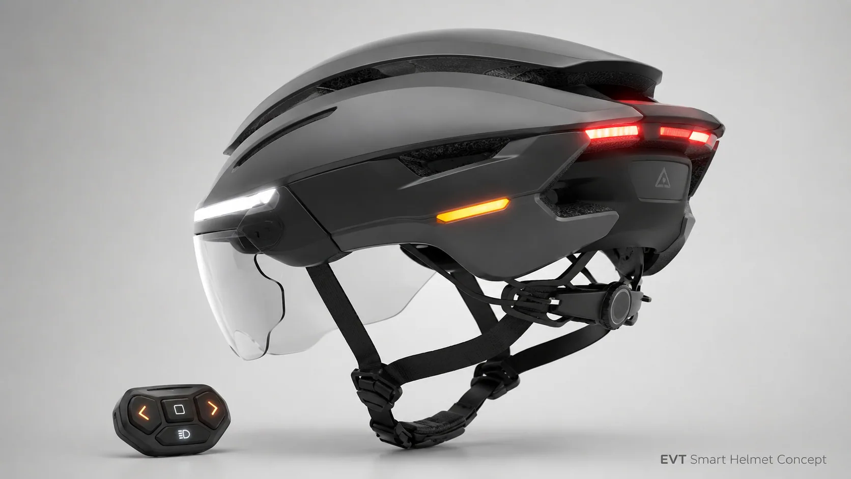
The EVT Smart Helmet uses a polycarbonate-class outer shell and EPS impact liner as the structural foundation. Lighting, electronics and energy storage are packaged in perimeter and rear zones selected to preserve the primary impact-management volumes and avoid hard contact points against the user.
Engineering detail Show
Forward conspicuity without becoming a fragile gadget bolted to the shell.
High-brightness rear signalling driven by validated deceleration events and manual overrides.
Cross-traffic visibility integrated into the shell perimeter.
Deceleration-event detection and a wireless handlebar controller for turn, hazard and headlight modes.
Visor, occipital dial, webbing and comfort padding engineered as part of the primary structure.
Protected charging path with controlled low-voltage and fault behaviour.
Surge Robotics design rule
Three coordinated layers: protect, sense and communicate.
Engineering detail Show
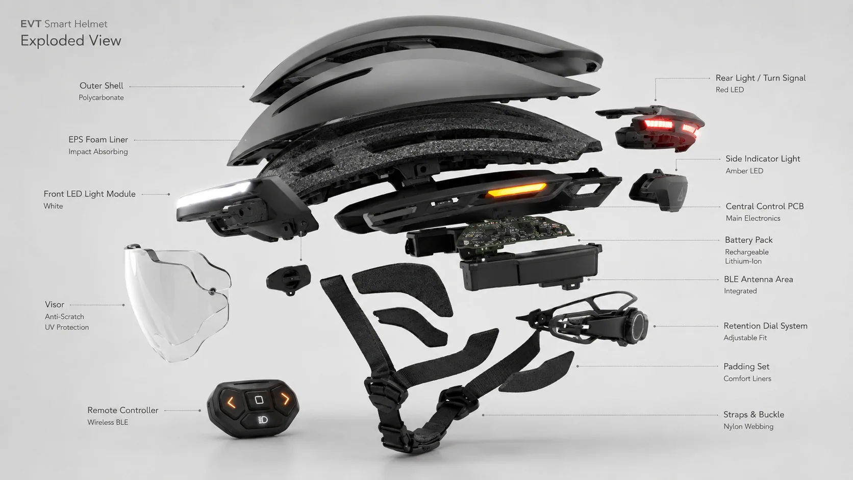
Outer shell, EPS liner, retention webbing, magnetic buckle, occipital dial, comfort pads and visor interfaces.
6-axis IMU, MCU, event filtering, battery supervision, mode logic and fault handling.
Front, side and rear LED drivers, BLE remote, user feedback and charging interface.
System priority hierarchy
Structure and retention are never subordinated to electronics packaging.
Manual hazard and turn commands override non-critical automatic effects.
Validated deceleration triggers rear brake illumination.
Headlight and running-light states follow rider selection.
Low-voltage and fault states shed loads predictably.
Electronics were packaged around the impact system — not through it.
The shell distributes local load and protects the EPS, while the liner manages impact energy through controlled crushing. PCB edges, cell housings, screws and connectors are isolated from the user and kept outside critical head-contact zones. Battery and control mass sit close to the head and are balanced laterally.
Engineering detail Show
Thin-wall moulding logic, local ribs, cosmetic surfaces and controlled openings.
Energy-management zones, air channels, component clearances and retention interfaces.
Separates optics and electronics from the crush liner and supports repeatable assembly.
Charging and user-access features are separated from non-serviceable safety elements.
Critical engineering constraint
The helmet has to remain stable, comfortable and intuitive before any smart function matters.
The occipital fit dial, webbing anchors and magnetic buckle were engineered for one-handed operation with gloves. The visor pivots and removability were tuned to remain positive across long rides and repeated cycles.

Engineering detail Show
Lighting zones & functions
Low-energy continuous visibility.
High-emphasis rear output after validated deceleration.
Directional side and rear indication with timeout.
Manual high-priority warning mode.
Brake-detection pipeline
Reliable brake detection required orientation-aware filtering and event confidence — not a single acceleration threshold.
- 1 — Sample — 6-axis IMU sampled at a fixed cadence with timestamped buffers.
- 2 — Orient — Head orientation estimated and gravity vector removed before analysis.
- 3 — Filter — Road shock, head nods and climbing posture rejected by shape and duration.
- 4 — Confirm — Deceleration event confirmed against confidence thresholds before rear light activation.
Safety boundary
The controller keeps signalling actions on the handlebar and the rider's eyes on the road.
A compact BLE remote provides left, right, hazard/mode and headlight functions. Pairing, reconnection, connection interval and advertising cadence were tuned for practical battery life and reliable behaviour after transient range or interference events.

Engineering detail Show
Secure first-time bond and stable rebonding across sessions.
Automatic reconnect after transient range or interference events.
Connection interval and advertising tuned for practical battery life.
A compact control platform coordinated sensing, radio, lighting and protected charging.

Engineering detail Show
- Battery + protected charging path with reverse, short-circuit and ESD protection
- MCU platform with sensor fusion, event arbitration and BLE stack
- LED drivers for front, side and rear zones with regulated output
- Accessible test pads for firmware and end-of-line diagnostics
- Controlled antenna keep-out inside the helmet assembly
Firmware state machine
Structured as a deterministic state machine with explicit event priorities.
| Off / shipping | Minimum current, protected wake-up and charger response. |
|---|---|
| Standby | Low-power idle with radio advertising and fast wake to active states. |
| Ride – position | Continuous running lights, IMU armed for brake events. |
| Ride – turn | Directional indication with automatic timeout and rider override. |
| Ride – hazard | Manual high-priority mode; overrides non-critical automatic effects. |
| Brake event | Validated deceleration triggers rear high-output pattern. |
| Charging | Protected charge state; high-output lighting states managed accordingly. |
| Fault / low-battery | Controlled load reduction, user indication, no random resetting. |
- Low voltage triggers controlled load reduction, not random reset cycling
- Sensor faults are detected and automatic functions degrade predictably
- Charging and high-output lighting states are mutually controlled where required
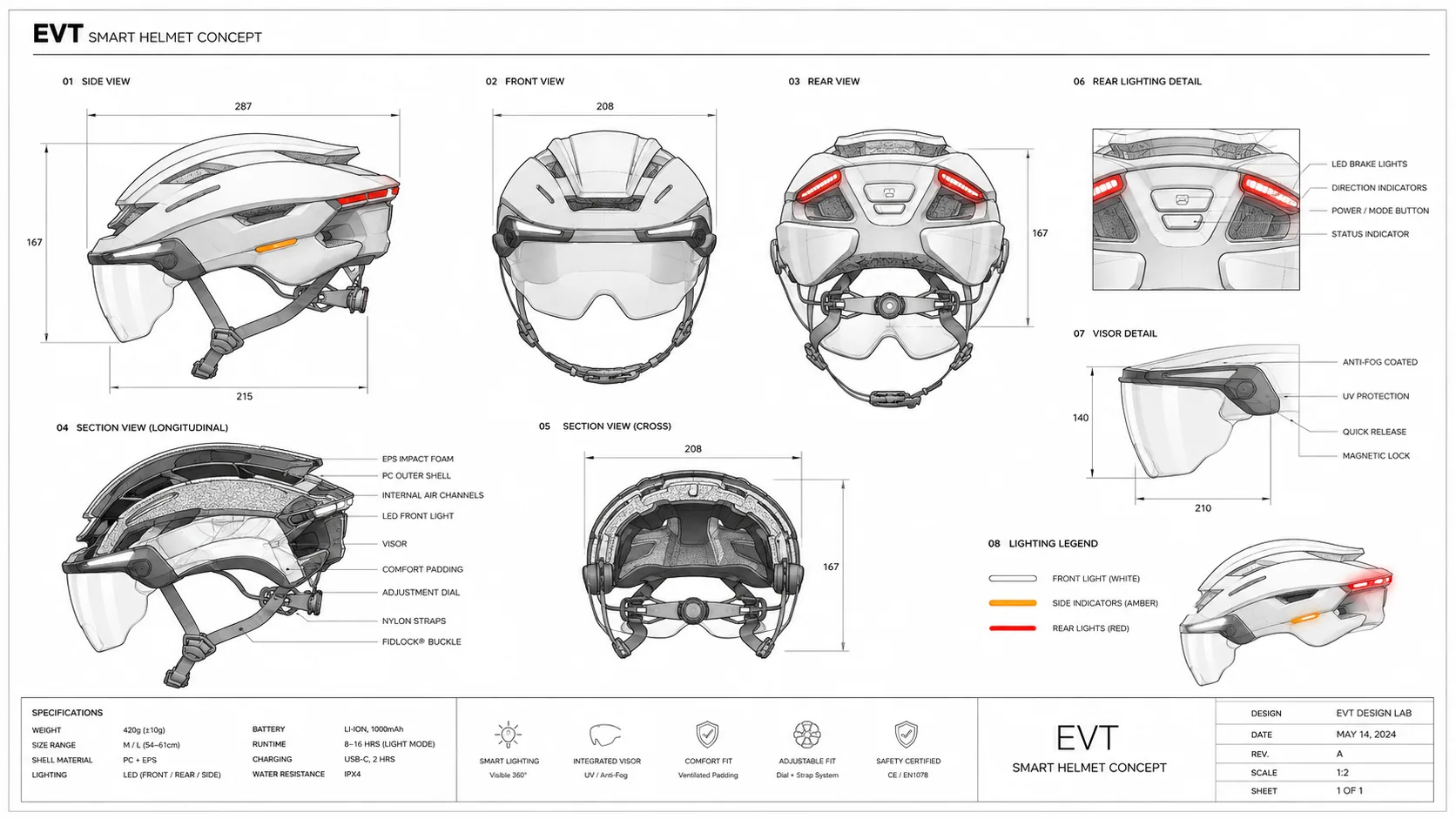
Rider ventilation, electronics cooling and water management were solved as separate but coordinated paths.
Ventilation channels, seams, USB-C cover, switches and lens interfaces were engineered so that thermal comfort and ingress behaviour do not compromise each other. Supplied revisions reference IPX4 and IPX5 targets; the released rating must follow validation of the exact production seams and assembly process.
Engineering detail Show
Ingress governance
Engineering detail Show
Mechanical & user system
| Target system mass | 410–420 g (controlled design range) |
|---|---|
| Reference fit range | 54–61 cm head circumference |
| Outer shell | Polycarbonate-class thin-wall moulding |
| Impact liner | EPS with defined energy-management zones |
| Retention | Occipital dial + webbing + magnetic buckle |
| Visor | Removable, pivoting, gloved operation |
| Ingress target | IPX4 / IPX5 (production release TBD) |
| Charging | USB-C with protected charging path |
Electronics, sensing & firmware
| Lighting | 3-zone: wide front, amber side, high-brightness rear |
|---|---|
| Sensing | 6-axis IMU with orientation-aware filtering |
| Compute | Embedded MCU with sensor fusion + BLE stack |
| Wireless controls | BLE handlebar remote — left, right, hazard, headlight |
| Power | Rechargeable battery, protected power states |
| Firmware states | Off, standby, ride, brake, charge, fault |
| Diagnostics | Test pads for firmware & EOL diagnostics |
| Update path | Controlled release channel |
SPECIFICATION CONTROL: THESE VALUES ARE DERIVED FROM THE SUPPLIED DESIGN REVISIONS. PRODUCTION SPECIFICATION MUST BE TAKEN FROM THE FINAL RELEASED BOM, DRAWINGS, FIRMWARE CONFIGURATION AND VERIFIED COMPLIANCE FILE.
One integrated engineering team across a safety-critical wearable product.
Engineering detail Show
Use cases, feature framing, safety boundaries and program success criteria.
Form language, CMF, visor integration and rider-visible signalling language.
Shell, EPS carriers, retention system, visor pivots, ingress strategy and hard-point control.
MCU platform, IMU, LED drivers, BLE radio, protected power path and charging.
State machine, event priorities, brake detection, low-power modes and diagnostics.
Sensor fusion, remote pairing, reconnection and connection-interval tuning.
Impact, retention, environmental, radio, battery and end-of-line test coverage.
Moulding strategy, assembly, fixtures, test coverage, supplier package and pilot support.
A 24-week reference programme organised around the highest-risk interfaces.
Engineering detail Show
01 / w1-2
Product definition & safety boundary
02 / w2-4
Concept & system architecture
03 / w3-6
Industrial design & CMF
04 / w5-12
Mechanical, EPS & retention
05 / w6-14
Electronics, firmware & BLE bring-up
06 / w12-18
Pilot-intent DVT & validation
08 / w20-24
DFM handoff & pilot production
Building a connected safety, mobility or wearable product?
Engineering detail Show
| Gate | Primary decision | Core deliverables | Release evidence |
|---|---|---|---|
| G0 | Product definition | Use cases, safety envelope, feature framing and program success criteria. | Approved PRD, safety boundary statement and risk baseline. |
| G1 | Architecture approval | Shell/EPS strategy, electronics packaging zones, sensing and BLE concept. | System architecture, ICD, feasibility studies and rig evidence. |
| G2 | Detailed design review | Shell, EPS, carriers, PCBs, firmware state machine and remote pairing. | Released prototype drawings, BOM, firmware baseline and procurement package. |
| G3 | Integrated EVT | Working helmet build, sensor bring-up, lighting integration and remote pairing. | EVT units, issue log, brake-detection evidence and validation plan. |
| G4 | Pilot-intent DVT | Production-representative materials, assembly and environmental exposure. | DVT verification report with pass/fail evidence and closed corrective actions. |
| G5 | Production release | DFM, assembly sequence, EOL fixtures, calibration and supplier support. | Production BOM, drawings, work instructions, inspection plan and release configuration. |
COMMERCIAL NEXT STEP: FREEZE A SINGLE MARKET CONFIGURATION, COMPLETE PRODUCTION-REPRESENTATIVE DVT BUILDS, EXECUTE ACCREDITED HELMET TESTING, CLOSE RADIO/BATTERY COMPLIANCE AND RUN A CONTROLLED PILOT BUILD WITH END-OF-LINE TEST COVERAGE.

Have a product you’d like us to engineer?
Share the product, challenge or technical risk you are facing. We’ll come back with a clear technical next step — no sales pitch disguised as discovery.